IGNITION SYSTEM
The ignition system is responsible for igniting the air/fuel mixture at the most appropriate time. To understand how the ignition system works in the mazda rx-7, it is important to have a good understanding of ignition systems in general. We'll start by giving a quick overview of ignition systems and then focus on the particularities of the ignition system in the mazda rx-7.
GENERIC IGNITION SYSTEM
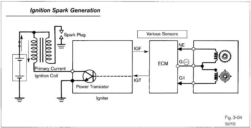
This above shows the schematics of a generic ignition system that one could find on many piston engine cars. The Ne signal indicates engine speed. The G1 signal indicates crankshaft angle. With these two sensors, the engine control monitor (ECM) has permanent knowledge of the crankshaft angle and the engine speed and therefore can tell when the spark plugs should be fired for optimum performance. The IGT (ignition timing) signal is a pulse which tells the igniter when the power transistor should switch off the current flowing through the primary winding of the ignition coil. This current is low voltage (12V). When current flows through the primary winding, it creates a magnetic field. When the current flow is cut suddenly, the magnetic field collapses inducing a high voltage current into the secondary winding. This high voltage current creates an arc at the spark and provides ignition. The IGF (ignition feedback) confirms to the ECM that a spark has ocurred.
MAZDA RX-7 IGNITION SYSTEM
There are two rotors in the rotary engine: a front rotor (rotor 1) and a rear rotor (rotor2). Each rotor has three combustion chambers. For each rotor revolution, there are three firing events. The eccentric shaft makes three revolutions for every rotor revolution, in other words, it turns at 1/3 the speed of the rotors. The two rotors are 60 degrees apart from each other.
There are two spark plugs for each rotor. The leading (L) spark plug is the main spark plug. The trailing (T) spark plug is here to complete the burn and reduce emissions. At idle and with no load, the leading spark plug fires at 5 degrees after top dead center (5ATDC) and the trailing spark plug fires at 20 degrees after top dead center (20ATDC). On a rotary engine, top dead center (TDC) happens when the combustion chamber (three per rotors) is centered on the two plugs.
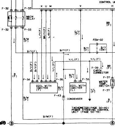
What follows is the electric diagram for the ignition system. This will give clues on how the system functions. Note that the engine control unit (ECU) relies upon an Ne and G signals from the crank angle sensor (CAS) to determine spark firing, as in a generic ignition system. These two signals will not be adressed any further here.
LEADING IGNITION
Consider the leading ignition coil with igniter on the schematics. The B/Y (black with yellow stripe) wire is the 12V primary current supply (from main relay). The G/Y (green with yellow stripe) carries the ignition timing signal (IGT-L) from the ECU. The IGT-L signal is a pulse. When the pulse switches from high to low, the igniter turns off the current in the primary leading coil winding. Since there is only one leading coil and there is no spark distribution, both leading spark plugs are arced. Obviously, one spark is wasted but with no ill effects. The leading ignition system is quite straightforward to comprehend. The trailing ignition system is more complex.
TRAILING IGNITION
The trailing ignition system is actually a two-coil system (one coil for each rotor). Consider the trailing ignition coil with igniter on the schematics. The B/Y (black with yellow stripe) wire is the 12V primary current supply (from main relay). This wire shows up twice in the wiring diagram since there are two coils. The L/Y (blue with yellow stripe) carries the ignition timing signal (IGT-T) from the ECU. The IGT-T signal is a pulse. The BR/Y (brown with yellow stripe) wire carries the ignition select signal (IGS-T) from the ECU. The IGS-T signal is a pulse. The L/R (blue with red stripe) wire carries the ignition feedback signal (IGF-T) back to the ECU. The IGF-T signal is a pulse (will not be addressed further here). The Y/L (yellow with blue stripe) wire carries a signal to the tachometer and check connector (not discussed further here). There is one ignition timing signal but there are two trailing coils. The ignition select signal tells the igniter which coil the ignition timing signal is for (see RX-7 ignition system for source of information). When the IGS-T signal switches from low to high, trailing coil 1 (for rotor 1) should be fired. When the IGS-T signal switches from high to low, trailing coil 2 (for rotor 2) should be fired.
Copyright © 2003 - The MAZDA RX-7 86-88 Technical Page - All Rights Reserved