CHARGING SYSTEM
How does it work ?
The charging system comprises the alternator and the battery. The battery is quite a passive component and will not be discussed here. The two main components of the alternator are the rotor and stator. The rotor consists of a coil of wire wrapped around an iron core. By supplying some DC current (field current) to the coil, the rotor becomes a magnet. The alternator pulley rotates the rotor inside the alternator. The stator is a set of three fixed coils spaced 120 degrees apart fixed to the alternator casing and surrounding the rotor. When the magnetized rotor rotates, it induces an AC current in each stator coil.
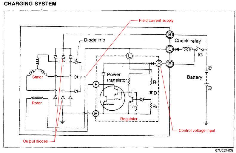
This above shows the schematics of the charging system. The regulator's function is to control the amount of current that is to pass through the rotor windings. The source for the current is the field current supply. The regulator looks at the control voltage input to determine how much of the field current supply should be fed to the rotor. The field current either comes from the battery (when the car is started) or the alternator itself via the diode trio (when the alternator can actually produce current). Because the current flowing in the stator coils is AC, it needs to be rectified. This rectification process is performed by two pairs (one for positive AC, the other for negative AC) of three output diodes (one for each stator coil). The alternator warning lamp (or check relay) is energized when the engine is started since the diode trio is not producing any current yet. When the engine is running, the warning lamp is not energized since there is now battery voltage at the field current supply point (shown in above schematics).
The B terminal corresponds to the post on top of the alternator. The L and R terminals connect to the back of the alternator via a connector. The L terminal (field current supply) is a W/B (white with black stripe) wire. The R terminal (control voltage input) is a B/W (black with white stripe) wire.
How do you check the alternator ?
The Factory Service Manual has a good series of tests for the alternator. They are reproduced here and explained. Please note that all those tests require a GOOD fully charged battery. Some of those tests require an ammeter to measure current draw (you can get an ammeter gauge and use it as your ammeter). It is a good idea to perfom all these tests and make sure the alternator passes all of them (not just the first one). When you measure voltage, you stick the positive lead of the multimeter to wherever the FSM tells you to and you stick the negative lead to the negative battery post which is the reference ground.
If any of the test fails and the reason it failed does not come from the wiring, I would replace the alternator with a quality replacement one and I would also replace the battery (a bad alternator is likely to have damaged the battery). If you are handy and know a little bit about electronics, you can certainly troubleshoot further and you may be able to pinpoint the problem exactly and act accordingly.
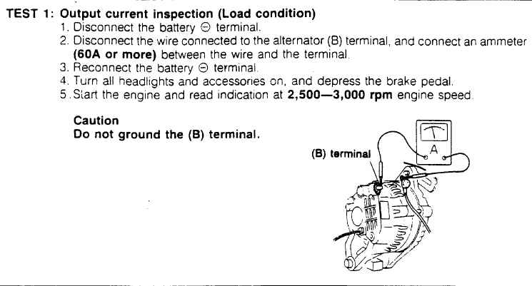
This test above checks to see if the alternator is able to produce enough current under maximum load (all electrical accessories on) at a high enough rpm (above 2500 rpm). The alternator passes this test if the output current is at least 55 A.
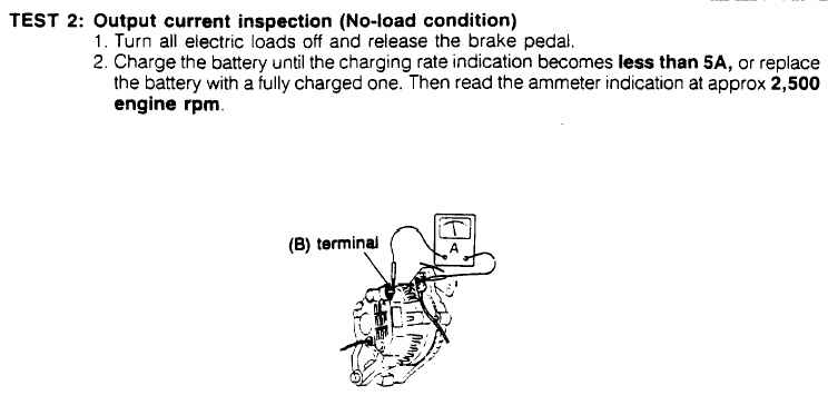
This test above checks if the alternator is providing the proper amount of current when there is no load (no electrical accessories on). For this test to be valid, the battery should be fully charged, meaning, it should draw less than 5 A when connected to battery charger (which is a must have). The alternator passes the test if the output current (at the B terminal) is less than 5 A.
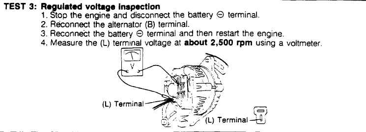
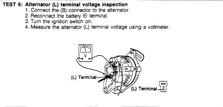
This test above checks the alternator's regulated output voltage with engine running. It is probably the first test that should be performed. The alternator passes the test if the voltage at the L terminal is between 14.4 and 15.0 V. Note that this results in the alternator warning light (all cluster lights and gear change light) being off.
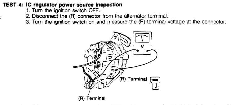
This test above checks the control voltage input to the alternator. The alternator passes the test if the voltage at the R connector is battery voltage (what you would get at the battery positive post). This test does not do much since it will only detect a fault in the wiring to the R connector.
This test above checks the alternator's regulated output voltage with engine off. The alternator passes the test if the voltage at the L terminal is 1 to 3 V. Note that this results in the alternator warning light (all cluster lights and gear change light) being on.
The S5 89-92 alternator conversion
Some people may want to put an alternator from the S5 89-92 models into their S4 86-88 car because it is rated at 80 A (70 A for the S4 alternator) or because it is available. It's plug and play mechanically wise but it's not electrically wise for two reasons: the plugs are of different shape and the connection of the R terminal (name S terminal on the S5 alt) is different.
If you look at the S5 alternator, you will see a little diagram showing where the L/S terminals are on the alternator. So, at this point, I assume you know where the L and S terminal are on the S5 alternator. Looking at the L/R plug in your S4 harness, you need to connect the W/B wire (L terminal of S4 alternator) to the L terminal of the S5 alternator using a couple of 1/4 inch crimp connectors and a small length of wire (please, solder wire before crimping). You DO NOT do anything with the B/W wire (R terminal of S4 alternator). The S5 alternator sees battery voltage at all times (even when ignition off) at its S terminal. This means that you connect the S terminal of the S5 alternator to some battery positive source, for example, the B terminal of the S5 alternator, the battery positive post or better yet, the EGI fuse. If you connect the B/W wire (R terminal of S4 alternator) to the S terminal of the S5 alternator, the battery will drain when ignition is off. If you wire it this way, the voltage regulator thinks the battery needs to be charged when ignition is off and therefore would allow current to go through the rotor coil if there is current available (via the B terminal).
Copyright © 2003 - The MAZDA RX-7 86-88 Technical Page - All Rights Reserved