Question: I don't understand the vacuum diagram shown in the FSM or Haynes manual ?
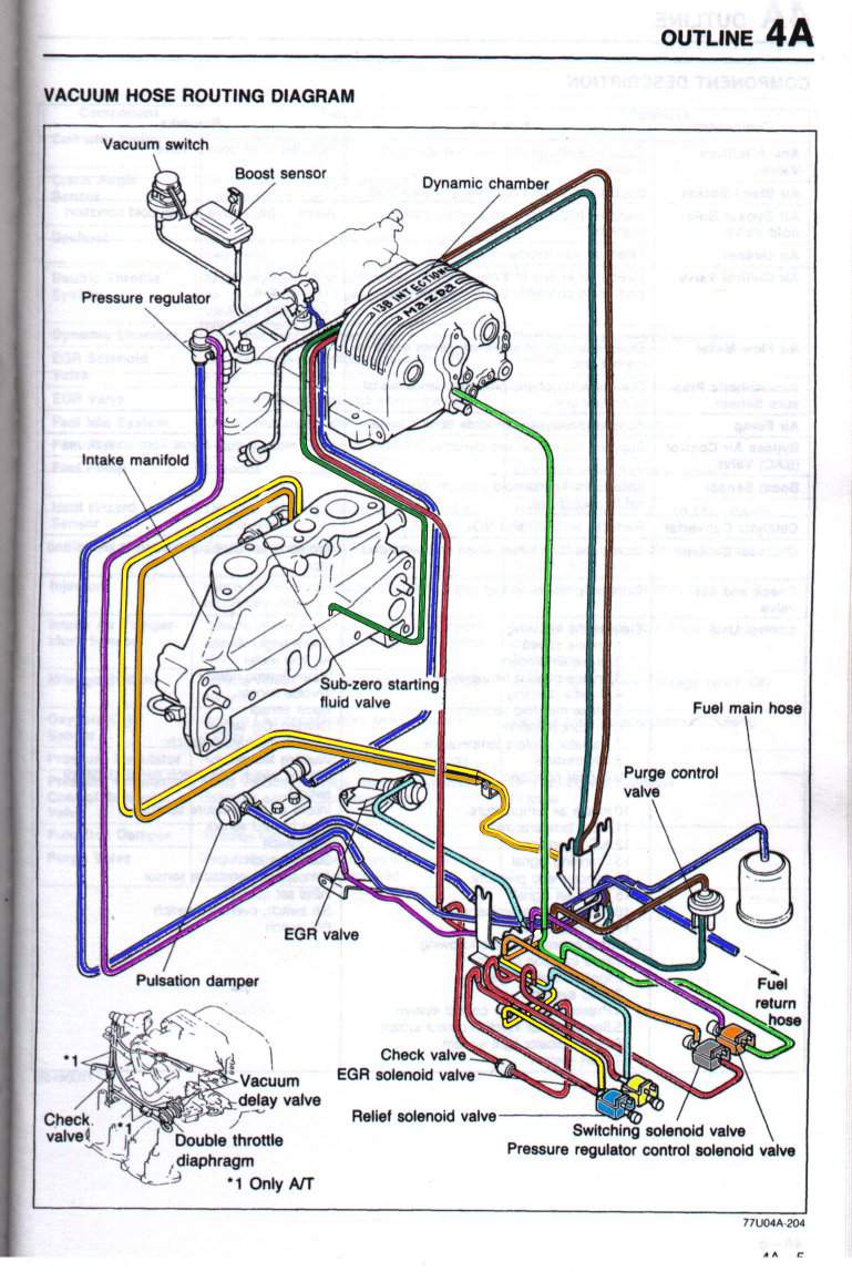
Do not worry, you are not alone. This colorized version makes it easier to distinguish the various vacuum lines and enables the following of the vacuum lines from beginning to end. I did not make this beautiful diagram. This originally came from a fellow by the name of "burntoast", then it landed on www.rx7club.com, and it was grabbed from there. There was an error in the diagram which I corrected (diagram is guaranteed to be 99% correct). The routing of the metal lines (rat's nest) is not well represented in the original FSM diagram so don't pay too much attention to it. What's important is where lines originate and terminate.
RELIEF, SWITCHING, AND EGR VALVES
The relief, switching, and EGR solenoid valves are connected to the same vacuum source (shown in red in the diagram). The vacuum line originating from a port at the front of the dynamic chamber (bottom nipple in that column of three) is teed into two lines: one that goes to the relief and switching solenoid valves and the other that goes to the EGR solenoid valve. The vacuum line going to the relief and switching solenoid valves is itself teed into two lines: one that goes to the relief solenoid valve and the other that goes to the switching solenoid valve. This double teeing makes the red portion of the diagram difficult to comprehend but it is actually straightforward if one follows what has just been said.
The relief solenoid valve connects to the relief valve via the yellow line. The switching solenoid valve connects to the switching valve via the orange line. The relief and switching valves are inside the ACV valve. The connections to those two valves are done via two nipples protruding slightly above the ACV valve at the top of the lower intake. The rear nipple (on the left when looking down at the ACV from the passenger side) is for the relief valve (as HAILERS on www.rx7club.com would say, rear is relief). The front nipple (on the right when looking down at the ACV from the passenger side) is for the switching valve. The EGR solenoid valve connects to the EGR valve via the light blue (aqua) line.
For more information on the relief and switching valves, please go to "emissions" and then "secondary air injection" from the main page.
For more information on the EGR valve, please go to "emissions" and then "exhaust gas recirculation" from the main page.
FUEL PRESSURE REGULATOR
The fuel pressure regulator control solenoid valve is connected to a vacuum source just underneath the Bypass Air Control (BAC) valve (shown in light green in the diagram).
The fuel pressure regulator control solenoid valve connects to the fuel pressure regulator via the purple line.
For more information on the fuel pressure regulator, please go to "fuel" from the main page.
PURGE VALVE
The purge valve connects to a pair of nipple in the rear of the dynamic chamber (firewall side if you will). The top of the purge valve is connected to the top nipple (shown in brown on the diagram). It is not a vacuum source since this leads to a port that is located in between the two sets of throttle plates. The bottom of the purge valve is connected to the bottom nipple (shown in that green blueish turquoise color on the diagram). It is a vacuum source since it goes to a port after the throttle plates.
The purge valve also connects to a port on the oil filler neck (not shown in diagram).
For more information on the purge valve, please go to "emissions" and then "crankcase and evaporative" from the main page.
MISCELLANEOUS
There are two nipples I have not talked about yet in that column of three at the front of the dynamic chamber. Well, it is about to change. The top nipple (larger one of the three) goes to the oil injector "spider" apparatus. It is not a vacuum port since it connects to somewhere in front of the two sets of throttle plates. The middle nipple connects to the fuel injector air bleeds(line shown in green on the diagram). It is not a vacuum port (I don't know where the intake port actually is so you will have to take my word for it).
The boost sensor connects to a nipple at the bottom of the upper intake to the right (I think) of the pair of nipples for the ACV.
Copyright © 2003 - The MAZDA RX-7 86-88 Technical Page - All Rights Reserved